NEMA Wiring Diagram Manual for Electrical Specialists
About 70% of the electrical failures in establishments result from inadequate wiring methods. Such data underlines the requirement of adhering to established standards, highlighting NEMA wiring diagrams’ value for electrical professionals. Via these schematics, wiring configurations that meet both performance productivity and optimal safety standards are presented.
The objective of this manual is to provide electrical practitioners with profound knowledge into NEMA standards. Stressing the value of accurate electrical setups is vital. Through mastering these rules, practitioners can drastically reduce the risk of accidents and confirm they adhere to safety protocols backed by Installation Parts Supply. Knowledge in l 14-30 plug is vital whether creating novel systems or servicing current ones, as it enhances the capability to deliver reliable and consistent electrical systems.
Essential Summaries
- NEMA wiring schematics are essential for ensuring electrical security and compliance.
- Adequate wiring practices can reduce electrical malfunctions considerably.
- Grasping NEMA norms boosts the effectiveness of electrical arrangements.
- Installation Parts Supply promotes adherence to safety protocols in electrical operations.
- NEMA diagrams support a variety of applications across different industries.
Comprehending NEMA Standards and Their Significance
NEMA norms are crucial in the electrical domain, directing protection and functionality meticulously. Formulated by the National Electrical Manufacturers Association, they set pivotal benchmarks for creating, testing, and marking electrical equipment. This ensures consistency and dependability across all electrical configurations, which is priceless.
Which Are NEMA Norms?
NEMA designations span from levels 1 through 13. Each level specifies the parameters required for electrical appliances to perform efficiently. For example, NEMA 1 offers basic indoor security but lacks dust protection. Conversely, NEMA 4 guarantees appliances is sealed, a must for withstanding substantial water contact. Grasping these classifications is essential in picking appropriate equipment.
How NEMA Norms Matter for Electrical Safety
The impact of NEMA standards in ensuring electrical security is significant. They play a significant part in minimizing electric shock, device breakdowns, and fire dangers. Proper adherence to NEMA ratings allows devices to perform securely under particular surrounding conditions. For open-air application, NEMA 3 classifications deliver protection against the weather, guarding the device from inclement climate like precipitation and snowfall. In areas at risk of explosions, standards including NEMA 7, 8, and 9 are critical for ensuring protection.
Implementations of NEMA Norms in Wiring Diagrams
The use of NEMA norms in wiring diagrams is vital for protected, efficient electrical installations. These diagrams employ uniform symbols and formats derived from NEMA ratings, simplifying the understanding of complex electrical configurations. Such standardization is advantageous. It encourages clarity, uniformity, and diminishes confusions, thus improving electrical protection across home and factory environments.
NEMA Wiring Diagram Essentials
NEMA wiring diagrams are crucial for electrical specialists, rendering complex junctions transparent. They describe the linkages and components in diverse configurations. By understanding the elements, types, and symbols of NEMA schematics, technicians can boost their work in deployments and servicing.
Constituents of NEMA Wiring Diagrams
NEMA schematics contain essential components for distinct electrical setups. You’ll discover wiring endpoints, connectors, and various hardware for reliable linkages. Every piece guarantees energy is spread optimally, following security standards.
Types of NEMA Wiring Schematics
NEMA employs multiple drawings, like connection diagrams and circuit designs. Such diagrams detail appliance interconnections, while designs show current flow. Choosing the right drawing helps with diagnostics and setup.
Typical Icons Used in NEMA Wiring Schematics
Symbols in wiring diagrams are crucial for clear communication. They illustrate switches, loops, and couplers. Knowing these notations assists groups interpret schematics properly. Thus, it guarantees setups adhere to NEMA norms.
NEMA Wiring Schematic Characteristics
For electrical specialists, comprehending the core elements of accurate electrical wiring diagrams is crucial. These schematics provide both clarity and thoroughness, synchronizing configurations with NEMA standards. They demand accurate marking and sizing to curtail installation errors. This encourages a more secure and highly efficient workplace.
Key Features of Correct Electrical Wiring Drawings
Accurate electrical wiring drawings are vital in electrical projects. They incorporate important attributes such as:
- Transparency: Schematics should be simple, reducing the risk of misinterpretation.
- Completeness: They must include all vital parts, linkages, and electrical standards.
- Conformance: Adherence to NEMA standards is mandatory for securing protection and performance.
- Detailed Labeling: Distinct labels on each component are essential for grasping and error prevention.
- Accurate Proportions: The dimensions should reflect the true setup to depict the system accurately.
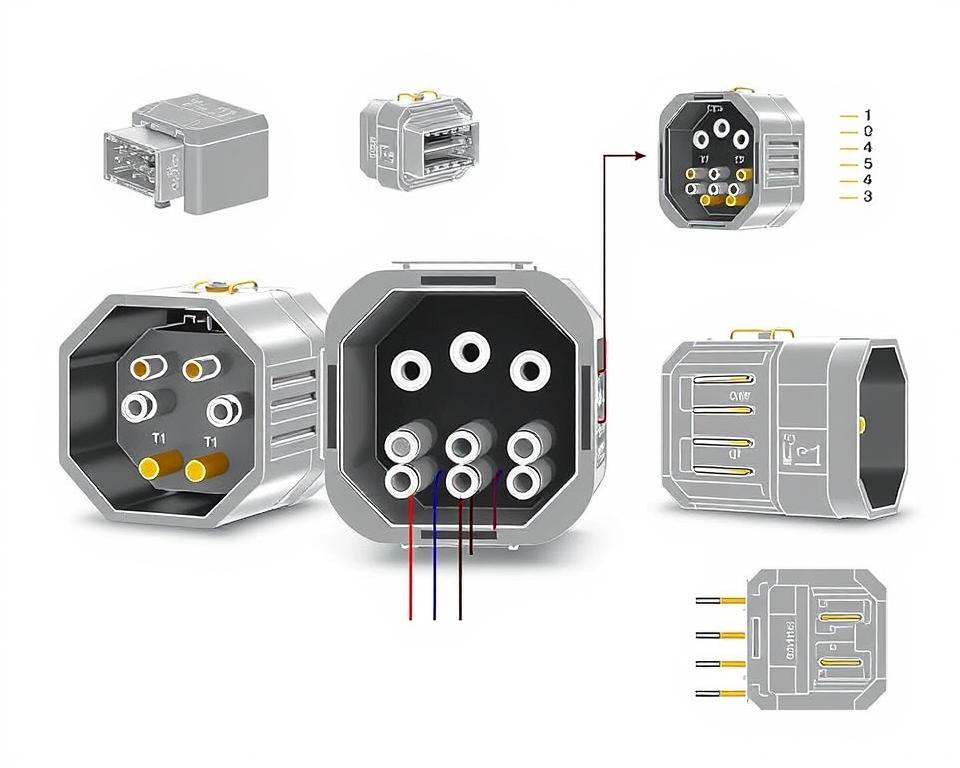
Understanding NEMA Connector Pinout
Understanding of NEMA connector layout is vital for forming proper connections in electrical systems. Understanding of particular pin setups ensures security and appliance functionality. There exists a range of NEMA interfaces, intended for different voltages and flows, covering:
| Connector Model | Amperage Rating | Voltage Rating |
|---|---|---|
| L5-15 | 15A | 125V |
| L5-20 | 20A | 125V |
| L14-20 | 20A | 125/250V |
| L1430C | 30A | 125/250V |
| L620C | 20A | 250V |
| L1430C | 30A | 125/250V |
| L630R | 30A | 250V |
Understanding NEMA connector layouts is crucial for reliable junctions, boosting effectiveness. It’s paramount to match couplers with appliances properly using twist-lock or linear blade styles, to avoid safety risks.
NEMA Device Wiring
NEMA device wiring covers multiple configurations for protected electrical appliance linkages. These guidelines confirm that devices integrate securely, lowering risk. Understanding the different NEMA equipment and their wiring is crucial for specialists.
Various Categories of NEMA Appliances
NEMA categorizes devices by kind based on voltage and current needs. Primary configurations are:
- 2-Pole 2-Wire
- 2-Pole, 3-Wire with Grounding
- 3-Pole 3-Wire
- 3-Pole, 4-Wire with Grounding
- 4-Pole 4-Wire
- 4-Pole 5-Wire Grounding
These configurations are employed in domestic settings and factories, supporting 125V, 208V, and 480V.
NEMA Plug Wiring Explained
NEMA plug wiring changes to accommodate multiple power needs, with rotary-lock types ensuring secure junctions in shaky settings. For instance, the L5-15 plug works at 15 amperes, common in enterprise settings, whereas the L14-20 is designed for 20 amps at 125/250 V.
The NEMA designation system helps in selecting the right plugs, spotlighting characteristics like electrical polarity and grounding. This meticulousness ensures that devices perform reliably.
NEMA Receptacle Wiring Instructions
Proper wiring of NEMA outlets meets electrical codes and safety norms. For instance, L530R receptacles should be wired for 30 amps at 125 volts, with L630R variants for 250 V. Adequate grounding is vital to prevent electrical errors.
Opting for certified NEMA plugs and sockets ensures safe, standard-compliant installations. It’s vital to refer to formal standards when setting up.
NEMA Motor Wiring and Uses
NEMA motor wiring is essential in electrical engineering, especially for manufacturing use. Knowing how NEMA motor setup works secures that engines are set up for optimal performance. These motors, like single-phase and three-phase models, require accurate wiring to work safely and efficiently.
Overview of NEMA Motor Wiring
Comprehending NEMA motor wiring requires knowledge of connections and arrangements. Nearly all three-phase motors offer dual-voltage, signifying they can operate at both low (208-230V) and high voltage levels (460V). High voltage wiring allows motors to draw less current than at low voltage. High voltage advantages include reduced gauge wiring for the power feed, a significant benefit for engines above 10 HP.
While both NEMA and IEC units are employed in the sector, NEMA models are typically more substantial and more expensive than IEC ones for less than 100 HP applications. NEMA starters span size 00 to 9, suitable for various applications. A typical attribute in NEMA starters is a Fault Class of 20, engineered to trigger when a motor’s current exceeds 6-fold the Full Load Amperage in 10 seconds.
Opting for the Appropriate NEMA Motor Arrangement
Opting for the appropriate NEMA motor setup impacts system performance and safety. A typical three-wire control circuit utilizes three wires for a on/off pushbutton interface, allowing straightforward motor operation. Common three-phase configurations include the 12 Lead Dual Voltage and 6 Lead, enabling Wye and Delta connections.
IEC motor starters frequently incorporate phase failure detection, enhancing safety. They also feature adjustable Trip Classes for customized protection in low voltage operations. Furthermore, many models have heat protection, essential for Single Phase and Dual Voltage configurations.
| Configuration Type | Voltage Level | Amperage | Usual Function |
|---|---|---|---|
| 12 Lead Dual Voltage | Dual Voltage (208-230V / 460V) | Dependent on motor size | Wye Start – Delta Run applications |
| 6 Lead | Single or Dual Voltage | 32 amps maximum | Both Wye and Delta arrangements |
| Single Phase | One Voltage | Dependent on adjustment (1-5A) | Dual Speed and Dual Winding setups |
| Delta Connection | Elevated Voltage | Based on configuration | Used for Current Transformers and various setups |
The Final Word
Grasping NEMA wiring schematics and standards is essential for electrical specialists looking to boost their expertise and adhere to electrical safety norms. These principles not only ensure safe and effective electrical installations but also avert dangers linked to improper wiring. As mentioned, adhering to NEMA norms results in the improved functionality of diverse NEMA devices and systems.
For electrical professionals, the choice of quality supplies can greatly affect the outcome of their work. Installation Parts Supply offers a extensive selection of wiring supplies in accordance with NEMA standards. This enables specialists to get critical parts for meeting these key standards. Premium resources and profound understanding of NEMA wiring diagrams greatly enhance project security and effectiveness.
Throughout electrical setups, always put security and exactness as a priority. Becoming well-versed in NEMA criteria delivers the insight needed for applying best practices accurately. This guarantees that every electrical junction made meets high-quality norms.
Frequently Asked Questions
What are NEMA wiring drawings?
NEMA wiring diagrams illustrate the configurations and linkages of NEMA-standard electrical appliances. They adhere to safety and performance criteria set by the National Electrical Manufacturers Association.
What makes NEMA criteria important for electrical safety?
NEMA norms are key to setting safety and performance criteria for electrical equipment. These standards help electrical experts minimize electric shock, device malfunctions, and burn dangers.
Which elements are essential in a NEMA wiring drawing?
Key elements in a NEMA wiring schematic consist of circuit configurations and linkage diagrams. These schematics also include comprehensive labels and illustrate the electrical system’s diverse parts precisely for installations.
What types of NEMA wiring schematics are used?
Diverse NEMA wiring drawings cater to diverse needs, including power distribution circuits and connector schematics. Each layout plays a distinct role in electrical installations.
Which are the typical symbols employed in NEMA wiring diagrams?
Typical symbols in these schematics depict toggles, circuit breakers, sockets, and more. Employing these symbols promotes effective communication and correct analysis of wiring drawings.
Identify the key characteristics of accurate electrical wiring schematics?
Accuracy in electrical wiring drawings is characterized by their clarity, comprehensiveness, and detailed annotation. They need to meet NEMA norms to avert errors in installation.
What is a NEMA connector layout?
A NEMA connector pinout outlines electrical connections at a connector, displaying distinct pin assignments. This guarantees safe and effective junctions in electrical networks.
Identify the different kinds of NEMA appliances?
NEMA devices comprise various electrical outlets and connectors, like connectors and outlets. They are designed for various ampere and power specifications to satisfy unique usage needs.
Describe how NEMA plug wiring set up?
NEMA plug wiring is determined by defined amperage and voltage levels needs, adhering to security protocols and code compliance for various electrical setups.
What guidelines are there for NEMA outlet wiring?
Recommendations for wiring NEMA sockets emphasize complying with electrical standards, guaranteeing proper polarity, and selecting proper gauge sizes. This ensures both protection and operation in electrical configurations.
How can I wire a NEMA motor properly?
To connect a NEMA motor, one must comprehend its defined single-phase or three-phase arrangement. Choosing the correct wiring approach is crucial, along with maintaining electrical protection for maximum motor functionality.
What must be taken into account when choosing a NEMA motor configuration?
Choosing a NEMA motor arrangement demands an evaluation of the project’s power needs and functional attributes. It’s also crucial to verify suitability with current systems for guaranteed performance and protection.